
Cadillac XT4 2025 Fuse Box Info
Passenger compartment fuse box location:
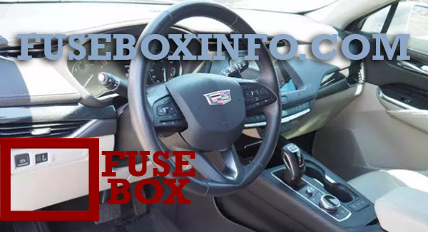
The instrument panel fuse box is on the driver side of the instrument panel, between the steering wheel and the door.
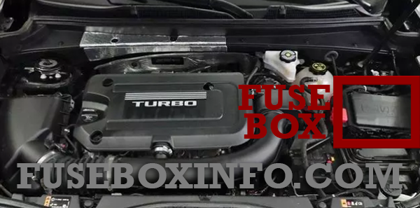
Engine compartment fuse box location:
Fuse Box Diagram | Layout
Passenger compartment fuse box:
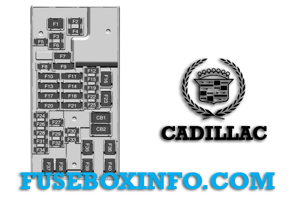
| Fuse/Relay N° | Functions |
| 1 | Blower Motor |
| 2 | ELM 1 – Exterior Lighting Module 1 |
| 3 | Column Lock |
| 4 | ELM 2 – Exterior Lighting Module 2 |
| 5 | BCM 2 – Body Control Module 2 |
| 6 | Amplifier |
| 7 | Clock Spring |
| 8 | DLC – Data Link Connector |
| 9 | BCM 1 – Body Control Module 1/SIB – Shifter Interface Board |
| 10 | Headliner/Auxiliary Switch |
| 11 | Display and HVAC |
| 12 | Steering Column Lock |
| 13 | Video Driving Monitoring System (DMS)/Safety 2 |
| 14 | RC MISC 3/ECM – Ride Control Miscellaneous 3/Electronic Control Module |
| 15 | Rear Wiper |
| 16 | Cargo APO – Cargo Auxiliary Power Outlet |
| 17 | Sensing Diagnostic Module (SDM)/Safety 1 |
| 18 | RC MISC 1/MISC 2 –Ride Control Miscellaneous 1/Miscellaneous 2 |
| 19 | Exterior Lighting Module (ELM) TR6 |
| 20 | Central Gateway Module(CGM)/Telematics (OnStar) |
| 21 | - |
| 22 | European Trailer |
| 23 | Auxiliary Power Outlet (APO) Cigar |
| 24 | Wireless Charger |
| 25 | USB |
| 26 | ELM 6 – Exterior Lighting Module 6 |
| 27 | VCU AUX JACK – Vehicle Communication Unit Auxiliary Jack |
| 28 | ELM 7– Exterior Lighting Module 7 |
| 29 | - |
| 30 | - |
| 31 | BCM 3 – Body Control Module 3 |
| 32 | HSWM – Heated Steering Wheel Module |
| 33 | - |
| 34 | STEERING CLMN ADJ MDL – Steering Column Adjacent Module |
| 35 | Amplifier |
| 36 | DC/DC BATT 2 |
| 37 | - |
| 38 | - |
| 39 | BCM 4 – Body Control Module 4 |
| 40 | - |
| CB01 | Auxiliary Power Outlet (APO) Row 2 |
| CB02 | Auxiliary Power Outlet (APO) Row 1 |
Engine compartment fuse box:
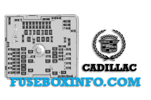
| Fuse/Relay N° | Functions |
| 1 | Spare |
| 2 | Aeroshutter |
| 3 | Spare |
| 4 | Spare |
| 5 | Spare |
| 6 | - |
| 7 | ECM 2 – Engine Control Module 2/ECM 3 – Engine Control Module 3 |
| 8 | ECM MAIN – Engine Control Module Main |
| 9 | - |
| 10 |
OFF ENG - |
| 11 | OFF ENG 2/OFF ENG 1 |
| 12 | CAC – Charge Air Cooler/ECM – Engine Control Module |
| 13 | TCM – Transmission Control Module |
| 14 | - |
| 15 | - |
| 16 | - |
| 17 | A/C Control |
| 18 | - |
| 19 | Starter Pinion |
| 20 | MCU – Microprocessor Control Unit |
| 21 | - |
| 22 | - |
| 23 | - |
| 24 | - |
| 25 | Starter Motor |
| 26 | Spare |
| 27 | - |
| 28 | - |
| 29 | - |
| 30 | - |
| 31 | - |
| 32 | Spare |
| 33 | Spare |
| 34 | ELM 5 – Exterior Lighting Module 5 |
| 35 | Power Sounder |
| 36 | ELM 4 – Exterior Lighting Module 4 |
| 37 | ELM 3 – Exterior Lighting Module 3 |
| 38 | MSM_E – Memory Seat Module |
| 39 | BSM – Battery State Module |
| 40 |
- Front Window Switch |
| 41 |
RDCM BATT 2 – Rear Drive Control Module Battery 2 - |
| 42 | Headlamp Right and Headlamp Left |
| 43 | FRT HTD SEAT MDL – Front Heated Seat Module |
| 44 | RFAM & AFL/RDCM BAT 2 – Radio Frequency Actuator Module and Adaptive Forward Lighting/Rear Drive Control Module Battery 2 |
| 46 | - |
| 47 | - |
| 48 | DC DC BAT 2 – Direct Current Direct Current Battery 2 |
| 49 | - |
| 50 | MTR WDW LIFTER LT – Motor Window Lifter Left |
| 51 | - |
| 52 | Passenger Power Seat |
| 53 | - |
| 54 | TIM 1 – Trailer Interface Module 1 |
| 55 | TIM 2 – Trailer Interface Module 2 |
| 56 | Trailer Park Lamps |
| 57 | RDCM BATT 1 – Rear Drive Control Module Battery 1 |
| 58 | Driver Power Seat |
| 59 | EBCM – Electronic Brake Control Module |
| 60 | Horn |
| 61 | Rear Defog |
| 62 | Front Wiper |
| 63 | Power Tailgate |
| 64 | MTR WDW LIFTER RT – Motor Window Lifter Right |
| 65 | - |
| 66 | Sunroof |
| 67 | Trailer Run |
| 68 | Spare |
| 69 | Spare |
| 70 | - |
| 71 | - |
| 72 | FTZM – Fuel Tank Zone Module |
| 73 | Handsfree Closure |
| 74 | - |
| 75 | Spare |
| 76 | Spare |
| 77 | Spare |
| 78 | Trailer Stop/Turn Left and Right |
| 79 | TCM (DC to DC) – Transmission Control Module |
| 80 | - |
| 81 | SADS – Semi Active Dampening Suspension |
| 82 | - |
| 83 | Washer Pump |