Honda Civic 2015 Fuse Box Info
Passenger compartment fuse box location:
The interior fuse box is located under the dashboard.
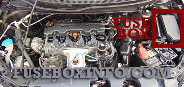
Engine compartment fuse box location:
Fuse Box Diagram | Layout
Passenger compartment fuse box:
| Fuse/Relay N° | Rating | Functions |
| 1 | (20A) | HAC Option* |
| 2 | 15A | ACG |
| 3 | 10A | SRS |
| 4 | 15A | Fuel Pump |
| 5 | 7.5A | Meter |
| 6 | 7.5A | Power Window |
| 7 | (15A) | VB SOL* |
| 8 | 15A | Door Lock Motor 2 (Unlock) |
| 9 | 15A | Door Lock Motor 1 (Unlock) |
| 10 | - | - |
| 11 | (20A) | Moonroof* |
| 12 | (15A) | Accessory Power Socket (Center Console)* |
| 13 | - | - |
| 14 | (15A) | Seat Heaters* |
| 15 | (10A) | Driver’s Door Lock Motor (Unlock)* |
| 16 | - | - |
| 17 | - | - |
| 18 | - | - |
| 19 | 7.5A | ACC |
| 20 | 7.5A | ACC Key Lock |
| 21 | 7.5A | Daytime Running Lights |
| 22 | 7.5A | HAC |
| 23 | (7.5A) | HAC* |
| 24 | 7.5A | ABS/VSA |
| 25 | (7.5A) | ACC* |
| 26 | - | - |
| 27 | 15A | Accessory Power Socket (Front) |
| 28 | 15A | Washer |
| 29 | 7.5A | ODS |
| 30 | (10A) | Driver’s Door Lock Motor (Lock)* |
| 31 | (10A) | SMART* |
| 32 | 15A | Door Lock Motor 2 (Lock) |
| 33 | 15A | Door Lock Motor 1 (Lock) |
| 34 | 7.5A | Small Lights |
| 35 | 7.5A | Illumination |
| 36 | - | - |
| 37 | - | - |
| 38 | 10A | Left Headlight High Beam |
| 39 | 10A | Right Headlight High Beam |
| 40 | (7.5A) | TPMS* |
| 41 | 20A | Door Lock |
| 42 | 20A | Driver’s Power Window |
| 43 | (20A) | Rear Passenger’s Side Power Window |
| 44 | 20A | Front Passenger’s Side Power Window |
| 45 | (20A) | Rear Driver’s Side Power Window |
| 46 | 30A | Wiper |
| - | (7.5A) | STS* |
* Not available on all models
Engine compartment fuse box:
| Fuse/Relay N° | Rating | Functions |
| 1 |
70A - 30A 30A 30A (30A) 100A |
EPS - ABS/VSA Motor ABS/VSA FSR Wiper Motor*2 -*3 Main Fuse |
| 2 |
30A*2/50A*3 60A 60A 30A 30A (30A) 30A 30A (30A) 40A (30A) 20A 20A |
IG Main Fuse Box Main Fuse Box Main 2 Headlight Main ST MG Switch*2 -*3 Rear Defogger IG Main 2*2 -*3 Blower - Sub Fan Motor Main Fan Motor |
| 3 | - | - |
| 4 |
- 10A |
-*2 Left Headlight Low Beam*3 |
| 5 |
7.5A 7.5A |
START DIAG*2 ST MG*3 |
| 6 |
- 15A |
-*2 Right Headlight Low Beam*3 |
| 7 | - | - |
| 8 | - | - |
| 9 | - | - |
| 10 | - | - |
| 11 | 7.5A | Oil Level |
| 12 | (20A) | Fog Lights* |
| 13 | (20A) | Driver’s Power Seat Sliding* |
| 14 | 10A | Hazard |
| 15 | 15A | FI Sub |
| 16 | 15A | IG Coil |
| 17 | 15A | Stop |
| 18 | 10A | Horn |
| 19 | (20A) | Premium Amp* |
| 20 |
15A (15A) |
Right Headlight Low Beam*2 Injection*,*3 |
| 21 | 15A | IGP |
| 22 | 15A | DBW |
| 23 |
15A 20A |
Left Headlight Low Beam*2 Headlight Low Beam*3 |
| 24 | (20A) | Driver’s Power Seat Reclining* |
| 25 | 7.5A | MG Clutch |
| 26 |
15A - |
Washer*2 -*3 |
| 27 | 20A | SMALL |
| 28 | 7.5A | Interior Lights |
| 29 | 10A | Backup |
* Not available on all models
*1: Models with the smart entry system have an ENGINE START/STOP button instead of an ignition switch.
*2: Models with smart entry system
*3: Models without smart entry system